Matriz LED 8×8 com Arduino Uno
Neste artigo iremos programar a matriz LED 8×8 usando o Arduino Uno. Para acompanhar este tutorial irá necessitar dos seguintes artigos,
| Imagem | Produto | Comprar |
|---|---|---|
|
|
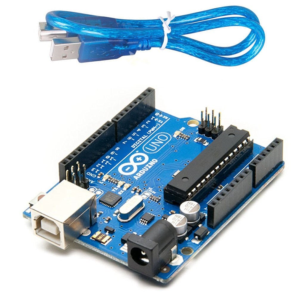
Arduino Uno |
|
|
|
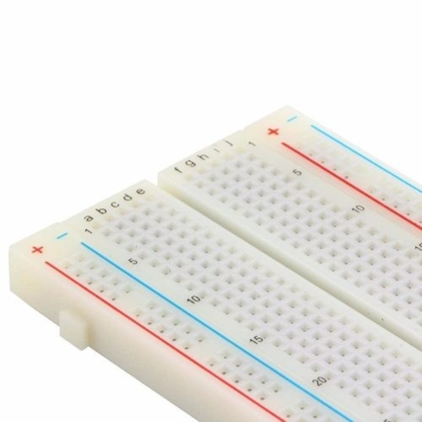
Breadboard |
|
|
|
Cabos Jumper Macho-Macho |
|
|
|
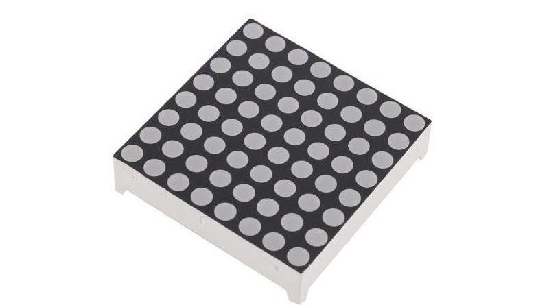
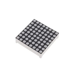
Matriz LED 8×8 |
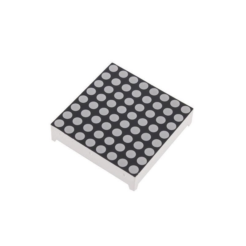
Sobre a Matriz LED 8×8
- LED de 3mm;
- Ânodo comum;
- Dimensões: 32 x 32 x 8mm (desconsiderando os terminais);
- Peso: 8.3g.
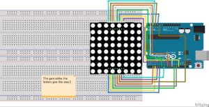
Esquema de Montagem
Código Utilizado
//update from SAnwandter

#define ROW_1 2
#define ROW_2 3
#define ROW_3 4
#define ROW_4 5
#define ROW_5 6
#define ROW_6 7
#define ROW_7 8
#define ROW_8 9

#define COL_1 10
#define COL_2 11
#define COL_3 12
#define COL_4 13
#define COL_5 A0
#define COL_6 A1
#define COL_7 A2
#define COL_8 A3

const byte rows[] = {
    ROW_1, ROW_2, ROW_3, ROW_4, ROW_5, ROW_6, ROW_7, ROW_8
};
const byte col[] = {
  COL_1,COL_2, COL_3, COL_4, COL_5, COL_6, COL_7, COL_8
};

// The display buffer
// It's prefilled with a smiling face (1 = ON, 0 = OFF)
byte ALL[] = {B11111111,B11111111,B11111111,B11111111,B11111111,B11111111,B11111111,B11111111};
byte EX[] = {B00000000,B00010000,B00010000,B00010000,B00010000,B00000000,B00010000,B00000000};
byte A[] = {  B00000000,B00111100,B01100110,B01100110,B01111110,B01100110,B01100110,B01100110};
byte B[] = {B01111000,B01001000,B01001000,B01110000,B01001000,B01000100,B01000100,B01111100};
byte C[] = {B00000000,B00011110,B00100000,B01000000,B01000000,B01000000,B00100000,B00011110};
byte D[] = {B00000000,B00111000,B00100100,B00100010,B00100010,B00100100,B00111000,B00000000};
byte E[] = {B00000000,B00111100,B00100000,B00111000,B00100000,B00100000,B00111100,B00000000};
byte F[] = {B00000000,B00111100,B00100000,B00111000,B00100000,B00100000,B00100000,B00000000};
byte G[] = {B00000000,B00111110,B00100000,B00100000,B00101110,B00100010,B00111110,B00000000};
byte H[] = {B00000000,B00100100,B00100100,B00111100,B00100100,B00100100,B00100100,B00000000};
byte I[] = {B00000000,B00111000,B00010000,B00010000,B00010000,B00010000,B00111000,B00000000};
byte J[] = {B00000000,B00011100,B00001000,B00001000,B00001000,B00101000,B00111000,B00000000};
byte K[] = {B00000000,B00100100,B00101000,B00110000,B00101000,B00100100,B00100100,B00000000};
byte L[] = {B00000000,B00100000,B00100000,B00100000,B00100000,B00100000,B00111100,B00000000};
byte M[] = {B00000000,B00000000,B01000100,B10101010,B10010010,B10000010,B10000010,B00000000};
byte N[] = {B00000000,B00100010,B00110010,B00101010,B00100110,B00100010,B00000000,B00000000};
byte O[] = {B00000000,B00111100,B01000010,B01000010,B01000010,B01000010,B00111100,B00000000};
byte P[] = {B00000000,B00111000,B00100100,B00100100,B00111000,B00100000,B00100000,B00000000};
byte Q[] = {B00000000,B00111100,B01000010,B01000010,B01000010,B01000110,B00111110,B00000001};
byte R[] = {B00000000,B00111000,B00100100,B00100100,B00111000,B00100100,B00100100,B00000000};
byte S[] = {B00000000,B00111100,B00100000,B00111100,B00000100,B00000100,B00111100,B00000000};
byte T[] = {B00000000,B01111100,B00010000,B00010000,B00010000,B00010000,B00010000,B00000000};
byte U[] = {B00000000,B01000010,B01000010,B01000010,B01000010,B00100100,B00011000,B00000000};
byte V[] = {B00000000,B00100010,B00100010,B00100010,B00010100,B00010100,B00001000,B00000000};
byte W[] = {B00000000,B10000010,B10010010,B01010100,B01010100,B00101000,B00000000,B00000000};
byte X[] = {B00000000,B01000010,B00100100,B00011000,B00011000,B00100100,B01000010,B00000000};
byte Y[] = {B00000000,B01000100,B00101000,B00010000,B00010000,B00010000,B00010000,B00000000};
byte Z[] = {B00000000,B00111100,B00000100,B00001000,B00010000,B00100000,B00111100,B00000000};

float timeCount = 0;

void setup()
{
    // Open serial port
    Serial.begin(9600);

    // Set all used pins to OUTPUT
    // This is very important! If the pins are set to input
    // the display will be very dim.
    for (byte i = 2; i <= 13; i++)
        pinMode(i, OUTPUT);
    pinMode(A0, OUTPUT);
    pinMode(A1, OUTPUT);
    pinMode(A2, OUTPUT);
    pinMode(A3, OUTPUT);
}

void loop() {
  // This could be rewritten to not use a delay, which would make it appear brighter
delay(5);
timeCount += 1;

if(timeCount <  20)
{
drawScreen(A);
}
else if (timeCount <  40)
{
drawScreen(R);
}
else if (timeCount <  60)
{
drawScreen(D);
}
else if (timeCount <  80)
{
drawScreen(U);
}
else if (timeCount <  100)
{
drawScreen(I);
}
else if (timeCount <  120)
{
drawScreen(N);
}
else if (timeCount <  140) {
  drawScreen(O);
}
else if (timeCount <  160)
{
drawScreen(ALL);
}
else if (timeCount <  180)
{
drawScreen(ALL);
}
else {
// back to the start
timeCount = 0;
}
}
 void  drawScreen(byte buffer2[])
 {
   // Turn on each row in series
    for (byte i = 0; i < 8; i++)        // count next row
     {
        digitalWrite(rows[i], HIGH);    //initiate whole row
        for (byte a = 0; a < 8; a++)    // count next row
        {
          // if You set (~buffer2[i] >> a) then You will have positive
          digitalWrite(col[a], (buffer2[i] >> a) & 0x01); // initiate whole column

          delayMicroseconds(100);       // uncoment deley for diferent speed of display
          //delayMicroseconds(1000);
          //delay(10);
          //delay(100);

          digitalWrite(col[a], 1);      // reset whole column
        }
        digitalWrite(rows[i], LOW);     // reset whole row
        // otherwise last row will intersect with next row
    }
}
//
  /* this is siplest resemplation how for loop is working with each row.
    digitalWrite(COL_1, (~b >> 0) & 0x01); // Get the 1st bit: 10000000
    digitalWrite(COL_2, (~b >> 1) & 0x01); // Get the 2nd bit: 01000000
    digitalWrite(COL_3, (~b >> 2) & 0x01); // Get the 3rd bit: 00100000
    digitalWrite(COL_4, (~b >> 3) & 0x01); // Get the 4th bit: 00010000
    digitalWrite(COL_5, (~b >> 4) & 0x01); // Get the 5th bit: 00001000
    digitalWrite(COL_6, (~b >> 5) & 0x01); // Get the 6th bit: 00000100
    digitalWrite(COL_7, (~b >> 6) & 0x01); // Get the 7th bit: 00000010
    digitalWrite(COL_8, (~b >> 7) & 0x01); // Get the 8th bit: 00000001
}*/
Sobre o código
- Pode alterar a letra da seguinte linha para personalizar o seu código: drawScreen(U);
- Pode adicionar letras e símbolos no seguinte formato, cada segmento representa uma linha, 0 LED Desligado e 1 LED Ligado:
- byte nomeByte[] = {B00000000,B00111100,B00000100,B00001000,B00010000,B00100000,B00111100,B00000000};
Para mais projetos, percorram o nosso blog, onde podem encontrar vários artigos interessantes relacionados com electrónica, robótica e muito mais! Visitem também o nosso site, onde encontram tudo para electrónica e robótica!