Módulo RF Transmissor e Recetor 433Mhz AM para Arduino e...
Precio
5,55 €
Precio base
6,53 €

(SEM IVA 6.55€)
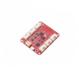
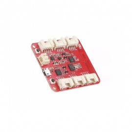
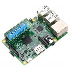
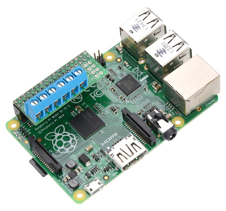
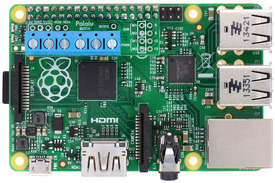
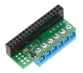
This compact expansion board plugs directly into the GPIO header on a Raspberry Pi B+, A+, or Pi 2 and provides an easy and low-cost solution for driving a pair of small brushed DC motors. Its integrated DRV8835 dual motor driver allows it to operate from 1.5 V to 11 V, making it a great control option for low-voltage motors.
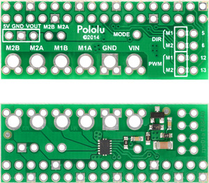
This motor driver kit and its corresponding Python library make it easy to control a pair of bidirectional, brushed DC motors with a Raspberry Pi Model B+, Model A+, or Pi 2 Model B. The expansion board features Texas Instruments’ DRV8835 dual H-bridge motor driver IC, which allows it to operate from 1.5 V to 11 V and makes it particularly well suited for driving small, low-voltage motors. The board can deliver a continuous 1.2 A per channel and tolerate peak currents up to 1.5 A per channel for a few seconds, and the channels can be optionally configured to run in parallel to deliver twice the current to a single motor. The board ships fully populated with its SMD components, including the DRV8835 driver and a FET for reverse battery protection; header pins for interfacing with a Raspberry Pi and terminal blocks for connecting motors and power are included but are not soldered in (see the Assembly with included hardware section below).
The board uses GPIO pins 5, 6, 12, and 13 to control the motor driver, making use of the Raspberry Pi’s hardware PWM outputs, although the pin mappings can be customized if the defaults are not convenient. Note that it is designed specifically for newer versions of the Raspberry Pi with 40-pin GPIO headers, including the Model B+, Model A+, and Raspberry Pi 2 Model B; it is not practical to use this expansion board with the original Raspberry Pi Model A or Model B due to differences in their pinout and form factor.
We also have a similar DRV8835 shield for Arduinos and Arduino-compatible boards and a smaller DRV8835 carrier for those using a different controller or with tighter space constraints. For a more powerful motor driver, consider the dual MC33926 motor driver for Raspberry Pi.
Although the DRV8835 itself works with a minimum motor supply voltage of 0 V, this board’s reverse-protection circuit limits the minimum to 1.5 V. If a lower motor supply voltage is required, please consider using our DRV8835 carrier with motor power supplied through the VMM pin.
Specifications:
•Dual-H-bridge motor driver: can drive two DC motors or one bipolar stepper motor
•Motor supply voltage: 1.5 V to 11 V
•Logic supply voltage 2 V to 7 V
•Output current: 1.2 A continuous (1.5 A peak) per motor
•Motor outputs can be paralleled to deliver 2.4 A continuous (3 A peak) to a single motor
•PWM operation up to 250 kHz (ultrasonic frequencies allow for quieter motor operation)
•Two possible interface modes: PHASE/ENABLE (default – one pin for direction, another for speed) or IN/IN (outputs mostly mirror inputs)
•Board can optionally power the Raspberry Pi base directly through add-on regulator (not included)
•Python library makes it easy to get started using this board as a motor driver expansion board
•GPIO pin mappings can be customized if the default mappings are not convenient
•Reverse-voltage protection on motor power supply
•Under-voltage lockout and protection against over-current and over-temperature
Assembly with included hardware
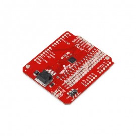
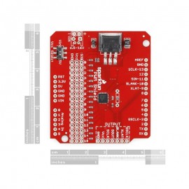
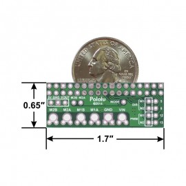
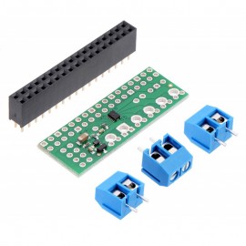
Before the motor driver board can be plugged into your Raspberry Pi, female headers must be soldered into the appropriate holes. The kit ships with a 2×17-pin 0.1? female header that should be mounted to the bottom of the board (the side with surface-mount components). Once the kit is assembled, it should be plugged into the leftmost position on the Raspberry Pi’s 40-pin GPIO header, leaving six pins exposed on the right, as shown in the picture below.
Three 2-pin, 5 mm terminal blocks are included for making easy motor and power connections to the board once they have been slid together and soldered to the six large through-holes. Alternatively, you can solder 0.1? male header pins to the smaller through-holes above the terminal block holes, or you can just solder wires directly to the board.
Shorting blocks and 0.1? male headers (not included) can be used to make some of the more advanced optional modifications to the board, such as remapping the control pins or paralleling the outputs.
Using the motor driver
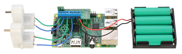
In the board’s default state, the motor driver and Raspberry Pi are powered separately, though they share a common ground and the DRV8835 receives its logic supply voltage (VCC) from one of the Raspberry Pi’s 3V3 power pins. When used this way, the Raspberry Pi must be powered via its USB Micro-B receptacle, and the motor driver board must be supplied with 1.5 V to 11 V through its large VIN and GND pads. However, the motor driver board provides a set of three through-holes where you can conveniently connect an appropriate voltage regulator, allowing the motor supply to also power the Raspberry Pi (see the Powering the Raspberry Pi from the motor driver board section below).
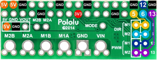
By default, the driver is configured to operate in PHASE/ENABLE mode, in which a PWM signal applied to the ENABLE pin determines motor speed and the digital state of the PHASE pin determines direction of motor rotation. GPIO 12 and 5 are used to control the speed and direction, respectively, of motor 1, and GPIO 13 and 6 control the speed and direction of motor 2.
Configuring the board for single-channel mode (parallel outputs)
In order to use the two motor channels in parallel to control a single motor, it is important to ensure that both channels will always receive the same control signals, so the reconfiguration process begins with a modification to the control inputs. First, locate the 2×4 grouping of 0.1? through-holes along the right side of the board. The traces on the underside of the PCB between each pair of holes effectively link the Raspberry Pi’s GPIO pins to the DRV8835 control pins. If you want to remap one of these control pins, you can cut the desired trace with a knife and then run a wire from the inner hole to a new GPIO pin. The remapping for single-channel mode requires you cut one PWM (12 or 13) and one DIR (5 or 6) trace. If you then solder a row of header pins along the interior row of holes, you can safely connect both PWM lines together and both DIR lines together using shorting blocks. In this configuration, the two uncut Raspberry Pi control lines determine the behavior of both motor channels.
The last step is to connect the output channels together. An easy way to do this is to solder wires to the two small holes labeled “M2A” and “M2B” above the motor outputs. You can then connect the M2A wire to the large M1A output pad and the M2B wire to the large M1B output pad, which in turn means you can get up to 3 A from the connection points for M2 (you can have your motor connected just to the M2A and M2B terminal blocks rather than trying to find a way to connect it to all four motor outputs).
Powering the Raspberry Pi from the motor driver board
On the left side of the expansion board is a set of three pins surrounded by a box and labeled “5V”, “GND”, and “VOUT”. The “5V” pin is connected to the Raspberry Pi’s 5V power rail, while the VOUT pin provides access to the driver board’s motor supply voltage after reverse-voltage protection. If a suitable voltage regulator is connected to these three pins, it can generate 5 V to power the Raspberry Pi from the board’s motor supply voltage. We suggest using our S7V7F5 switching step-up/step-down regulator, which has a 2.7 V to 11.8 V input voltage range (similar to that of the DRV8835) and can supply up to 1 A of current to the Raspberry Pi.
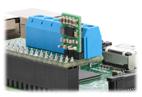
S7V7F5 step-up/step-down regulator connected to an assembled Pololu DRV8835 Dual Motor Driver Kit for Raspberry Pi.
When adding a voltage regulator to the motor driver board, take care to orient it correctly: note that the motor driver board’s VOUT pin should connect to the regulator’s VIN pin, while the regulator’s VOUT pin should connect to the motor driver board’s 5V pin.
There are several considerations to keep in mind when powering the Raspberry Pi through a voltage regulator in this way:
You must never connect a different power supply to the Raspberry Pi (including through its USB Micro-B receptacle) while the regulator is connected, as doing so will create a short between the voltage regulator’s output and the external power supply that could permanently damage the Raspberry Pi, the regulator, and/or the power supply.
Your motor power supply must be an acceptable voltage for both your regulator and the DRV8835.
The regulator should be able to handle the power requirements of the Raspberry Pi. The Raspberry Pi typically uses a few hundred milliamps at 5 V (depending on the specific model), although its current draw can exceed 1 A if it is also supplying power to USB devices and other peripherals. While linear regulators like a 7805 might fit in the regulator mounting location, they could generate excessive heat or shut down at higher input voltages and output currents. We recommend using a switching regulator (like our S7V7F5, as mentioned above).
Real-world power dissipation considerations:
The DRV8835 datasheet recommends a maximum continuous current of 1.5 A per motor channel. However, the chip by itself will overheat at lower currents. For example, in our tests at room temperature with no forced air flow, the chip was able to deliver 1.5 A per channel for approximately 15 seconds before the chip’s thermal protection kicked in and disabled the motor outputs, while a continuous current of 1.2 A per channel was sustainable for many minutes without triggering a thermal shutdown. The actual current you can deliver will depend on how well you can keep the motor driver cool. Our tests were conducted at 100% duty cycle; PWMing the motor will introduce additional heating proportional to the frequency.
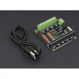
Este Driver diseñado para Micro: Bit, es ultra eficiente y versátil y ofrece innumerables posibilidades para sus robots móviles inteligentes.
This compact expansion board plugs directly into the GPIO header on a Raspberry Pi B+, A+, or Pi 2 and provides an easy and low-cost solution for driving a pair of small brushed DC motors. Its integrated DRV8835 dual motor driver allows it to operate from 1.5 V to 11 V, making it a great control option for low-voltage motors.