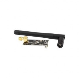
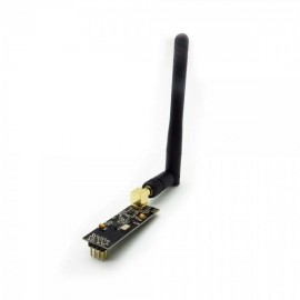
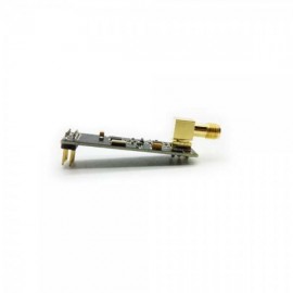
O Módulo NRF24L01 sem fios 2.4G de longo alcance é baseado no chip nRF24L01+ e nele contém o circuito PA e o circuito LNA. Com a antena externa, o Módulo NRF24L01 pode atingir uma distância muito mais longa do que o mesmo sem esta parte.
O módulo de rede Wireless NRF24L01 é uma óptima opção de comunicação entre placas como Raspberry Pi e Arduino, trabalhando na frequência de 2.4GHz.
Este módulo transmissor sem fios, NRF24L01, é um módulo fácil e adequado se quiser configurar o seu sistema de comunicação sem fios e a baixo custo!
Com este módulo, pode enviar e receber informações à distância de sensores, microcontroladores, máquinas e equipamentos electrónicos em geral. Além disso, este módulo nRF24L01 + é projetado com amplificador de potência e antena SMA. Isso permite utilizar a comunicação sem fios até 1000 metros! (sem barreiras)
Especificações:
• Controlador NRF24L01+ (datasheet);
• Frequência: 2.4GHz~2.5GHz;
• Tensão de operação: 3 ~ 3.6V Máx.;
• Corrente: 115mA;
• Multi-frequência: 125 frequência.
Inclui:
• 1x Módulo NRF24L01;
• 1x Antena SMA.
Código Exemplo:
/** ******************************************************************
**   SPI-compatible                                                 **
**   CS -  to digital pin 8                                         **
**   CSN - to digital pin 9   (SS pin)                              **
**   IRQ - to digital pin 10  (IRQ pin)                             **
**   MOSI - to digital pin 11 (MOSI pin)                            **
**   MISO - to digital pin 12 (MISO pin)                            **
**   CLK - to digital pin 13  (SCK pin)                             **
*********************************************************************/

#include <SPI.h>
#include "API.h"
#include "nRF24L01.h"

//***************************************************
#define TX_ADR_WIDTH    5   // 5 unsigned chars TX(RX) address width
#define TX_PLOAD_WIDTH  32  // 32 unsigned chars TX payload

unsigned char TX_ADDRESS[TX_ADR_WIDTH]  =
{
  0x34,0x43,0x10,0x10,0x01
}; // Define a static TX address

unsigned char rx_buf[TX_PLOAD_WIDTH] = {0}; // initialize value
unsigned char tx_buf[TX_PLOAD_WIDTH] = {0};
//***************************************************
void setup()
{
  Serial.begin(9600);
  pinMode(CE,  OUTPUT);
  pinMode(CSN, OUTPUT);
  pinMode(IRQ, INPUT);
  SPI.begin();
  delay(50);
  init_io();                        // Initialize IO port
  unsigned char sstatus=SPI_Read(STATUS);
  Serial.println("*******************TX_Mode Start****************************");
  Serial.print("status = ");
  Serial.println(sstatus,HEX);     // There is read the mode’s status register, the default value should be ‘E’
  TX_Mode();                       // set TX mode
}

void loop()
{
  int k = 0;
  for(;;)
  {
    for(int i=0; i<32; i++)
        tx_buf[i] = k++;
    unsigned char sstatus = SPI_Read(STATUS);                   // read register STATUS's value
    if(sstatus&TX_DS)                                           // if receive data ready (TX_DS) interrupt
    {
      SPI_RW_Reg(FLUSH_TX,0);
      SPI_Write_Buf(WR_TX_PLOAD,tx_buf,TX_PLOAD_WIDTH);       // write playload to TX_FIFO
    }
    if(sstatus&MAX_RT)                                         // if receive data ready (MAX_RT) interrupt, this is retransmit than  SETUP_RETR
    {
      SPI_RW_Reg(FLUSH_TX,0);
      SPI_Write_Buf(WR_TX_PLOAD,tx_buf,TX_PLOAD_WIDTH);      // disable standy-mode
    }
    SPI_RW_Reg(WRITE_REG+STATUS,sstatus);                     // clear RX_DR or TX_DS or MAX_RT interrupt flag
    delay(1000);
  }
}

//**************************************************
// Function: init_io();
// Description:
// flash led one time,chip enable(ready to TX or RX Mode),
// Spi disable,Spi clock line init high
//**************************************************
void init_io(void)
{
  digitalWrite(IRQ, 0);
  digitalWrite(CE, 0);			// chip enable
  digitalWrite(CSN, 1);                 // Spi disable
}

/************************************************************************
**   * Function: SPI_RW();
 *
 * Description:
 * Writes one unsigned char to nRF24L01, and return the unsigned char read
 * from nRF24L01 during write, according to SPI protocol
************************************************************************/
unsigned char SPI_RW(unsigned char Byte)
{
  return SPI.transfer(Byte);
}

/**************************************************/

/**************************************************
 * Function: SPI_RW_Reg();
 *
 * Description:
 * Writes value 'value' to register 'reg'
/**************************************************/
unsigned char SPI_RW_Reg(unsigned char reg, unsigned char value)
{
  unsigned char status;

  digitalWrite(CSN, 0);                   // CSN low, init SPI transaction
  SPI_RW(reg);                            // select register
  SPI_RW(value);                          // ..and write value to it..
  digitalWrite(CSN, 1);                   // CSN high again

  return(status);                   // return nRF24L01 status unsigned char
}
/**************************************************/

/**************************************************
 * Function: SPI_Read();
 *
 * Description:
 * Read one unsigned char from nRF24L01 register, 'reg'
/**************************************************/
unsigned char SPI_Read(unsigned char reg)
{
  unsigned char reg_val;

  digitalWrite(CSN, 0);                // CSN low, initialize SPI communication...
  SPI_RW(reg);                         // Select register to read from..
  reg_val = SPI_RW(0);                 // ..then read register value
  digitalWrite(CSN, 1);                // CSN high, terminate SPI communication

  return(reg_val);                     // return register value
}
/**************************************************/

/**************************************************
 * Function: SPI_Read_Buf();
 *
 * Description:
 * Reads 'unsigned chars' #of unsigned chars from register 'reg'
 * Typically used to read RX payload, Rx/Tx address
/**************************************************/
unsigned char SPI_Read_Buf(unsigned char reg, unsigned char *pBuf, unsigned char bytes)
{
  unsigned char sstatus,i;

  digitalWrite(CSN, 0);                   // Set CSN low, init SPI tranaction
  sstatus = SPI_RW(reg);       	    // Select register to write to and read status unsigned char

  for(i=0;i<bytes;i++)
  {
    pBuf[i] = SPI_RW(0);    // Perform SPI_RW to read unsigned char from nRF24L01
  }

  digitalWrite(CSN, 1);                   // Set CSN high again

  return(sstatus);                  // return nRF24L01 status unsigned char
}
/**************************************************/

/**************************************************
 * Function: SPI_Write_Buf();
 *
 * Description:
 * Writes contents of buffer '*pBuf' to nRF24L01
 * Typically used to write TX payload, Rx/Tx address
/**************************************************/
unsigned char SPI_Write_Buf(unsigned char reg, unsigned char *pBuf, unsigned char bytes)
{
  unsigned char sstatus,i;

  digitalWrite(CSN, 0);                   // Set CSN low, init SPI tranaction
  sstatus = SPI_RW(reg);             // Select register to write to and read status unsigned char
  for(i=0;i<bytes; i++)             // then write all unsigned char in buffer(*pBuf)
  {
    SPI_RW(*pBuf++);
  }
  digitalWrite(CSN, 1);                   // Set CSN high again
  return(sstatus);                  // return nRF24L01 status unsigned char
}
/**************************************************/

/**************************************************
 * Function: TX_Mode();
 *
 * Description:
 * This function initializes one nRF24L01 device to
 * TX mode, set TX address, set RX address for auto.ack,
 * fill TX payload, select RF channel, datarate & TX pwr.
 * PWR_UP is set, CRC(2 unsigned chars) is enabled, & PRIM:TX.
 *
 * ToDo: One high pulse(>10us) on CE will now send this
 * packet and expext an acknowledgment from the RX device.
 **************************************************/
void TX_Mode(void)
{
  digitalWrite(CE, 0);

  SPI_Write_Buf(WRITE_REG + TX_ADDR, TX_ADDRESS, TX_ADR_WIDTH);    // Writes TX_Address to nRF24L01
  SPI_Write_Buf(WRITE_REG + RX_ADDR_P0, TX_ADDRESS, TX_ADR_WIDTH); // RX_Addr0 same as TX_Adr for Auto.Ack

  SPI_RW_Reg(WRITE_REG + EN_AA, 0x01);      // Enable Auto.Ack:Pipe0
  SPI_RW_Reg(WRITE_REG + EN_RXADDR, 0x01);  // Enable Pipe0
  SPI_RW_Reg(WRITE_REG + SETUP_RETR, 0x1a); // 500us + 86us, 10 retrans...
  SPI_RW_Reg(WRITE_REG + RF_CH, 40);        // Select RF channel 40
  SPI_RW_Reg(WRITE_REG + RF_SETUP, 0x07);   // TX_PWR:0dBm, Datarate:2Mbps, LNA:HCURR
  SPI_RW_Reg(WRITE_REG + CONFIG, 0x0e);     // Set PWR_UP bit, enable CRC(2 unsigned chars) & Prim:TX. MAX_RT & TX_DS enabled..
  SPI_Write_Buf(WR_TX_PLOAD,tx_buf,TX_PLOAD_WIDTH);

  digitalWrite(CE, 1);
}